Products
- Temporary anchor
Contact Us
Information
고객센터
맴버쉽
Product Questions
SW-RCD Anchor
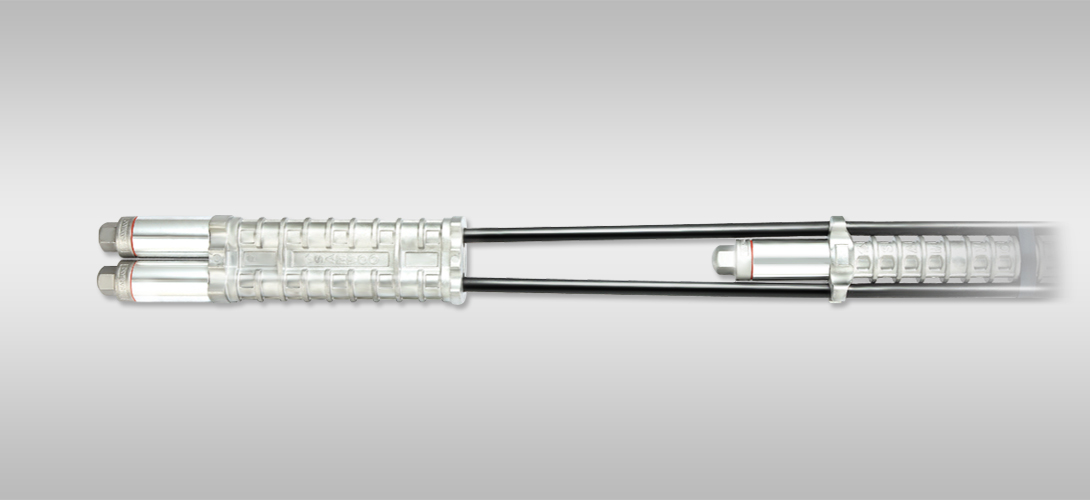
Removable, Compressive
and load Distributive type Anchor
(SW-RCD Anchor) The SW-RCD anchor is a load distributive compression type removable anchor that offers a complete solution where anchorage systems required to be removed once they become redundant. Often city municipalities and the like, object to obstructions left in the ground beyond completion of construction for fear they will conflict with future developments or seek third party approval. The SW-RCD anchors are a cost effective solutions where the use of conventional tieback anchors are forbidden or discarded due to logistical and or practical site constraints. The entire steel strand can be quickly and easily removed or reengaged with limited site access. Simply rotate the strand to release the wedges which are fixed in the end of the anchor body and the entire steel strand is easily withdrawn through the PE sheath leaving the small aluminum anchor body. The removal process is generally done by hand. In addition, allowing the steel strand to penetrate through the inside and be secured to the end of the anchor body, distributes the jacking force along the length of the anchor body which maximizes the effective cross-sectional area of the grout body. Since their initial development of these anchors have been employed in numerous projects around the world, providing lateral support to temporary sheeting and shoring conditions.
- SW-RCD Features
- 1 The anchor load is distributed and applied uniformly along the bond length which is ideal for relatively instable soils such as clay.
- 2 No. of steel strands are freely adjustable according to the design loads and soil conditions
- 3 Maximum design load of 3,300kN can be achieved when utilizing a combination of sextuple anchor bodies.(The value is based on the 24nos of 15.7mm dia. Steel strands)
- 4 The HDPE sheath provides a high quality, uninterrupted plastic bond breaker and additional corrosion protection.
- 5 Steel strand can be easily removed or reengaged to the body by simply rotating the strand with a pair of pliers. Therefore, site access and removal process are minimized.
- 6 The strands are individually secured to the end of the anchor body which maximizes the design performance and reduces eccentricity.
- 7 Load distributive compression type anchors uniformly distribute the jacking force to the soil which minimize creep and potential for resulting load loss.
- 8 Anchors are manufactured in a semi-automated standardized facility resulting in stringent quality control and outstanding quality assurance.
- 9 Anchors are fully assembled and packaged in coils for delivery and job site convenience. The packaging is also ideal for long-term storage of anchors.
Principles of SW-RCD Anchor Removal
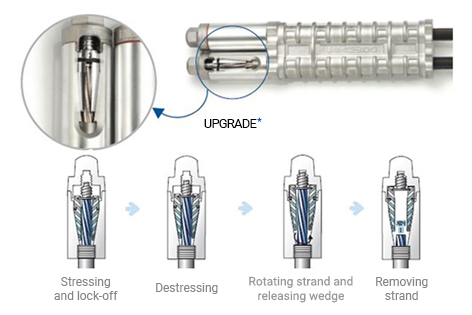
- 1 Destressing
- 2 Rotate steel strand clockwise and release wedge.
- 3 Manually remove steel strand separated from the wedge.
UPGRADE
The newly developed corrosion-protection aluminum die-casting anchor body
More improved component with precision and combination method
High-tech structure for strand protection and prevention of grout infiltration
SW-RCD
Anchor Guidelines 1. Pre-grouting (1st) should be done through the borehole before the installation of RCD anchor and 2nd grouting (filling the borehole) can be done with pulling out the casing.
2. Compressive strength of the grout should be over 30 MPa for proper load transfer through the anchor body during stressing process.
3. Stressing for each strand with mono jacks is strongly recommended to avoid any excessive load concentration to shorter strands (Step-by-step stressing with one normal jack could be applied as an alternative without mono jacks to cover the elongation gap between the strands with different length)
4. Each anchor body should be cleaned without any contamination before installation.
5. Steel support should be combined only with the 1st anchor body before installation to avoid dirty materials in the bottom of the borehole.
6. PE sheath should not be damaged during handling and installation in the jobsite to avoid any grout infiltration to the damaged sheath (Major reason not to rotate the strand and removal of the strand is not possible)
SW-RCD Anchor : Design/Specifications
Table 1. SW-RCD Anchor Specification (15.24mm) (ASTM A416 270 Grade, Low Relaxation)
[ASTM-A-416]
| No. of Steel strand (φ = 15.24mm) | Ultimate Strength (kN) |
Yield Strength (kN) |
Allowable Design Load (Ta) (kN) |
Remarks |
|---|---|---|---|---|
| 3 | 782 | 704 | 391 |
*Ultimate Strength (Breaking Load) (Tu) = 260.7KN (1 strand) *Yieid Strength (Load at 1% Elongation) (Ty) = 234.6kN (1 strand) *Allowable Design Load (Ta) = 0.5 Tu *Allowable Lock-off Load = 1.1 Ta *Stressing Load = 0.8 Tu Reference BS-8081:2015 |
| 4 | 1,043 | 938 | 521 | |
| 5 | 1,304 | 1,173 | 652 | |
| 6 | 1,564 | 1,408 | 782 | |
| 7 | 1,825 | 1,642 | 912 | |
| 8 | 2,086 | 1,877 | 1,043 | |
| 9 | 2,346 | 2,111 | 1,173 | |
| 10 | 2,607 | 2,346 | 1,304 | |
| 11 | 2,868 | 2,581 | 1,434 | |
| 12 | 3,128 | 2,815 | 1,564 | |
| Max, 24 | 6,257 | 5,630 | 3,128 |
Table 2. SW-RCD Anchor Specification (15.70mm) (BS-5896 Super Grade, Low Relaxation)
[BS-5896]
| No. of Steel strand (φ = 15.70mm) | Ultimate Strength (kN) |
Yield Strenght (kN) |
Allowable Design Load (Ta) (kN) |
Remarks |
|---|---|---|---|---|
| 3 | 837 | 738 | 419 |
*Ultimate Strength (Breaking Load) (Tu) = 279KN (1 strand) *Yieid Strength (Load at 1% Elongation) (Ty) = 246kN (1 strand) *Allowable Design Load (Ta) = 0.5 Tu *Allowable Lock-off Load = 1.1 Ta *Stressing Load = 0.8 Tu Reference BS-8081:2015 |
| 4 | 1,167 | 984 | 558 | |
| 5 | 1,395 | 1,230 | 698 | |
| 6 | 1,674 | 1,476 | 837 | |
| 7 | 1,953 | 1,722 | 977 | |
| 8 | 2,232 | 1,968 | 1,116 | |
| 9 | 2,511 | 2,214 | 1,256 | |
| 10 | 2,790 | 2,460 | 1,395 | |
| 11 | 3,069 | 2,706 | 1,535 | |
| 12 | 3,348 | 2,952 | 1,674 | |
| Max, 24 | 6,696 | 5,904 | 3,348 |
Available strand standard
-15.2mm (AS/NZ 4672) / 15.2mm (KS D 7002) / 12.7mm (KS D 7002)
![]()
149, Yangpyeong-ro, Yeongdeungpo-gu, Seoul
TEL : +82-2-2679-2380
FAX : +82-2-2634-6912
Copyright © SAMWOOGEOTECH CO, LTD. All Rights Reserved.