Products
- Temporary anchor
Contact Us
Information
고객센터
맴버쉽
Product Questions
SW-PTF Anchor
Permanant,
Tensile and Frictional type Anchor
(SW-PTF Anchor) The SW-PTF, conventional tension type permanent, anchors have long been used for a variety of purposes throughout the world. The rust and corrosion resistance property of this anchoring system is ideal for permanent support of structures. The SW-PTF is used largely for permanent sheathing and shoring, tiedown anchors to resist buoyancy forces, slope stability and landslide control as well as numerous other applications.
-
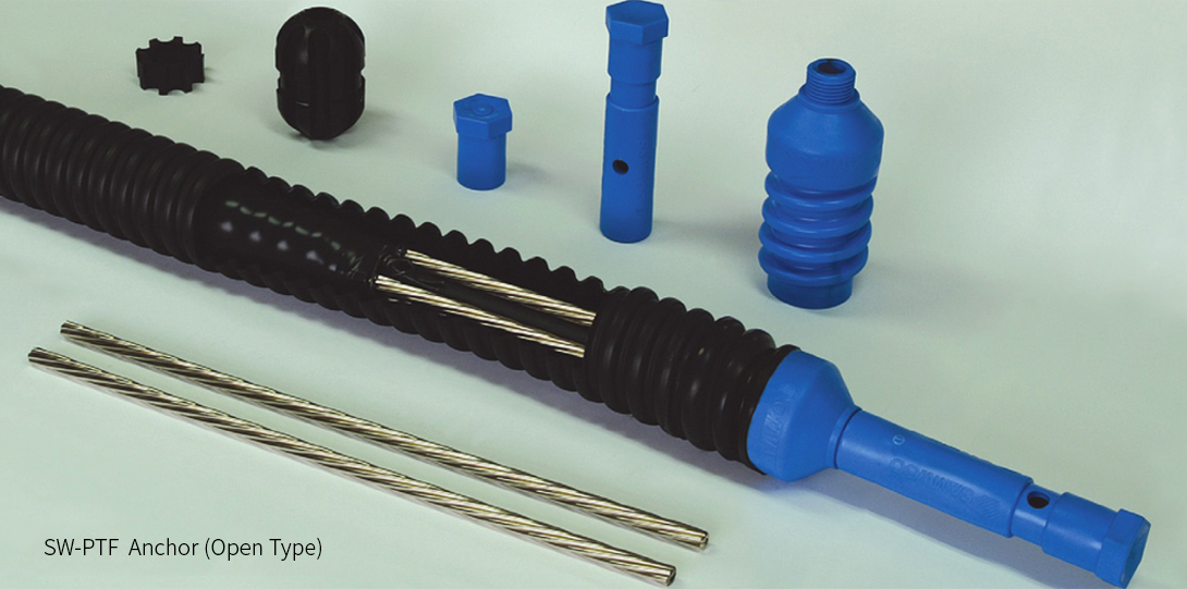
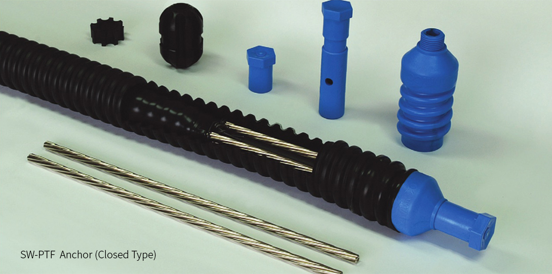
- SW-PTF Anchor Features
- 1 Steel strand and corrugated sheath is freely adjustable according to design load and depth of installation.
- 2 Anchors are manufactured in a semi-automated standardized facility resulting in stringent quality control and outstanding quality assurance.
- 3 Anchors are fully assembled and packaged in coils for delivery and job site convenience. The packaging is also ideal for long-term storage of anchors.
- 4 Plastic nose cone used at the distal end of the anchor provides clearance at the end of borehole adding additional protection and resistance to corrosion.
- 5 The both single protection and double protection can be supplied depending on client's request.
Detail of PTF Anchor

Design/ Specifications
Table 1. SW-PTF Anchor Specification (15.24mm) (ASTM A416 270 Grade, Low Relaxation)
[ASTM A-416]
| No. of Steel strand (φ = 15.24mm) |
Ultimate Strength (kN) |
Yield Strength (kN) |
Allowable Design Load (Ta) (kN) |
Duct Size I.D/O.D (mm) |
Remarks |
|---|---|---|---|---|---|
| 3 | 782 | 704 | 391 | 65/85 | * Ultimate Strength (Breaking Load) (Tu) = 260.7KN (1 strand) * Yieid Strength (Load at 1% Elongation) (Ty) = 234.6kN (1 strand) * Allowable Design Load (Ta) = 0.5 Tu * Allowable Lock-off Load = 1.1 Ta * Stressing Load = 0.8 Tu Reference BS-8081:2015 |
| 4 | 1,043 | 938 | 521 | ||
| 5 | 1,304 | 1,173 | 652 | 80/105 | |
| 6 | 1,564 | 1,408 | 782 | ||
| 7 | 1,825 | 1,642 | 912 | ||
| 8 | 2,086 | 1,877 | 1,043 | ||
| 9 | 2,346 | 2,111 | 1,173 | 100/130 | |
| 10 | 2,607 | 2,346 | 1,304 | ||
| 11 | 2,868 | 2,581 | 1,434 | ||
| 12 | 3,128 | 2,815 | 1,564 | ||
| 13 | 3,389 | 3,050 | 1,695 | ||
| 14 | 3,650 | 3,284 | 1,825 | ||
| 15 | 3,911 | 3,519 | 1,955 | ||
| 16 | 4,171 | 3,754 | 2,086 | 125/160 | |
| 17 | 4,432 | 3,988 | 2,216 | ||
| 18 | 4,693 | 4,223 | 2,346 | ||
| 19 | 4,953 | 4,457 | 2,477 | ||
| 20 | 5,214 | 4,692 | 2,607 | ||
| 21 | 5,475 | 4,927 | 2,737 | ||
| 22 | 5,735 | 5,161 | 2,868 | ||
| 23 | 5,996 | 5,396 | 2,998 | ||
| 24 | 6,257 | 5,630 | 3,128 | ||
| 25 | 6,518 | 5,865 | 3,259 | ||
| 38 | 9,907 | 8,915 | 4,953 | 150/188 | |
| 49 | 12,774 | 11,495 | 6,387 | 175/230 or 200/260 |
* According to required anchor design load, the strand number can be increased for SW-PTF Anchor.
Table 2. SW-PTF Anchor Specification (15.70mm) (BS-5896 Super Grade, Low Relaxation)
[BS-5896]
| No. of Steel strand (φ = 15.70mm) |
Ultimate Strength (kN) |
Yield Strength (kN) |
Allowable Design Load (Ta) (kN) |
Duct Size I.D/O.D (mm) |
Remarks |
|---|---|---|---|---|---|
| 3 | 837 | 738 | 419 | 65/85 | * Ultimate Strength (Breaking Load) (Tu) = 279.0KN (1 strand) * Yieid Strength (Load at 1% Elongation) (Ty) = 246.0kN (1 strand) * Allowable Design Load (Ta) = 0.5 Tu * Allowable Lock-off Load = 1.1 Ta * Stressing Load = 0.8 Tu Reference BS-8081:2015 |
| 4 | 1,116 | 984 | 558 | ||
| 5 | 1,395 | 1,230 | 698 | 80/105 | |
| 6 | 1,674 | 1,476 | 837 | ||
| 7 | 1,953 | 1,722 | 977 | ||
| 8 | 2,232 | 1,968 | 1,116 | 100/130 | |
| 9 | 2,511 | 2,214 | 1,256 | ||
| 10 | 2,790 | 2,460 | 1,395 | ||
| 11 | 3,069 | 2,706 | 1,535 | ||
| 12 | 3,348 | 2,952 | 1,674 | ||
| 13 | 3,627 | 3,198 | 1,814 | ||
| 14 | 3,906 | 3,444 | 1,953 | 125/160 | |
| 15 | 4,185 | 3,690 | 2,093 | ||
| 16 | 4,464 | 3,936 | 2,232 | ||
| 17 | 4,743 | 4,182 | 2,372 | ||
| 18 | 5,022 | 4,428 | 2,511 | ||
| 19 | 5,301 | 4,674 | 2,651 | ||
| 20 | 5,580 | 4,920 | 2,790 | ||
| 21 | 5,859 | 5,166 | 2,930 | ||
| 22 | 6,138 | 5,412 | 3,069 | ||
| 36 | 10,044 | 8,856 | 5,022 | 150/188 | |
| 49 | 13,671 | 12,054 | 6,836 | 175/230 or 200/260 |
* According to required anchor design load, the strand number can be increased for SW-PTF Anchor.
SW-PTF
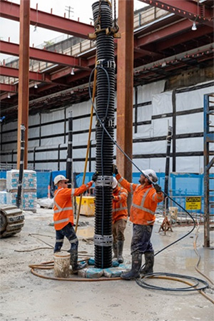
Anchor Guidelines 1. Avoid damaging corrugated sheath to prevent water infiltration and corrosion issues.
2. Care shall be taken when lowering anchor into borehole to prevent damaging nose-cone. Sudden impact to bottom of borehole can damage cone resulting in external grouting difficulty and anchor performance issues.
3. Care shall be taken to prevent damaging PE sheath covering steel strand. Damage to PE sheath may result in wire corrosion resulting in permanent anchor classification issues.
4. When storing or moving anchors at constructions site, it is important that the anchor bodies are not soiled with dirt or foreign debris. Anchor contamination will result in a decrease in bond, grout compressive strengths, and overall anchor performance.
5. Caution is required to prevent collapsing of borehole when inserting anchor. Grout voids in bore hole will result in reduced anchor capacity.
![]()
149, Yangpyeong-ro, Yeongdeungpo-gu, Seoul
TEL : +82-2-2679-2380
FAX : +82-2-2634-6912
Copyright © SAMWOOGEOTECH CO, LTD. All Rights Reserved.