Products
- Temporary anchor
Contact Us
Information
고객센터
맴버쉽
Product Questions
SW-PCD Anchor
Permanant,
Compressive
and load Distributive type Anchor
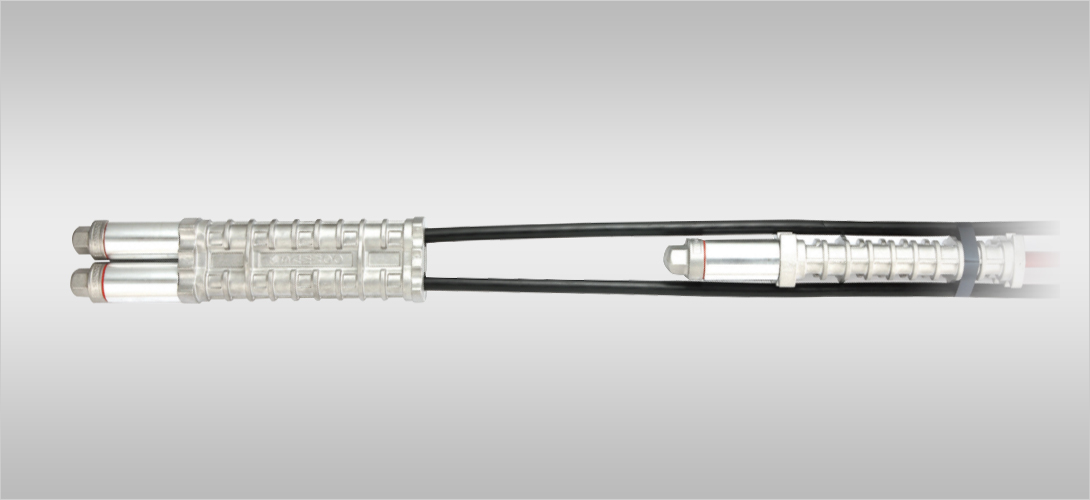
(SW-PCD Anchor) The SW-PCD anchor is a load distributive compression type permanent anchor which utilizes Individually greased and PE extruded strand for outstanding rust and corrosion resistance. The SW-PCD anchor is manufactured so that the Individually greased and PE extruded strand penetrates through the inside and secures to the end of the anchor body. This design distributes the jacking force along the length of the anchor body which maximizes the effective cross-sectional area of the grout body. Therefore, the compressive force transferred to the grout body is much higher than that of conventional compression type anchors. The SW-PCD anchors are used largely for permanent sheathing and shoring, tiedown anchors to resist buoyancy forces, slope stability and landslide control as well as numerous other applications.
Compressive
and load Distributive type Anchor
(SW-PCD Anchor) The SW-PCD anchor is a load distributive compression type permanent anchor which utilizes Individually greased and PE extruded strand for outstanding rust and corrosion resistance. The SW-PCD anchor is manufactured so that the Individually greased and PE extruded strand penetrates through the inside and secures to the end of the anchor body. This design distributes the jacking force along the length of the anchor body which maximizes the effective cross-sectional area of the grout body. Therefore, the compressive force transferred to the grout body is much higher than that of conventional compression type anchors. The SW-PCD anchors are used largely for permanent sheathing and shoring, tiedown anchors to resist buoyancy forces, slope stability and landslide control as well as numerous other applications.
- SW-PCD Anchor Features
- 1 The anchor load is distributed and applied uniformly along the bond length which is ideal for relatively unstable soils such as clay.
- 2 The aluminum anchor body and corrosion resistance housing protects the SW-PCD anchor and provides a highly corrosion resistant system.
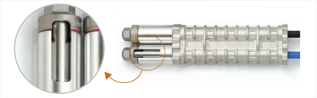
- 3 Corrosion resistant Individually greased and PE extruded strands penetrate through and are individually secured to the end of anchor body with greased grippers / end blocks placed inside galvanized / stainless steel sleeves and end caps with rubber rings. This assembly also offers outstanding corrosion protection.
- 4 No. of steel strands are freely adjustable according to the design loads and soil conditions.
- 5 Maximum design load of 3,300kN can be achieved when utilizing a combination of sextuple anchor bodies (value based on 15.7mm dia. steel strand x 24 strands)
- 6 Load distributive compression type anchors uniformly distribute the jacking force to the soil which minimizes creep and potential for resulting load loss.
- 7 Anchors are manufactured in a semi-automated standardized facility with state of the art equipment resulting in stringent quality control and outstanding quality assurance.
- 8 Anchors are fully assembled and packaged in coils for delivery and job site convenience. The packaging is also ideal for long-term storage of anchors.
SW-PCD Anchor Technology
UPGRADE
The newly developed corrosion-protection aluminum die-casting anchor body
More improved component with precision and combination method
High-tech structure for strand protection and prevention of grout infiltration
SW-PCD
Anchor Guidelines 1. Care shall be taken so not to damage extruded steel strand coating. Damage to coating may result in wire corrosion resulting in permanent anchor classification issues.
2. When storing or moving anchors at constructions site, it is important that the anchor bodies are not soiled with dirt or foreign debris. Anchor contamination will result in a decrease in bond and grout compressive strengths and overall anchor performance.
3. Caution is required to prevent collapsing of borehole when inserting anchor. Grout voids in bore hole will result in reduced anchor capacity.
Design/Specifications
Table 1. SW-PCD Anchor Specification (15.24mm) (ASTM A416 270 Grade, Low Relaxation)
[ASTM A416]
| No. of Steel strand (φ = 15.24mm) | Ultimate Strength (kN) |
Yield Strength (kN) |
Allowable Design Load (Ta) (kN) |
Remarks |
|---|---|---|---|---|
| 3 | 782 | 704 | 391 |
* Ultimate Strength (Breaking Load) (Tu) = 260.7KN (1 strand) * Yieid Strength (Load at 1% Elongation) (Ty) = 234.6kN (1 strand) * Allowable Design Load (Ta) = 0.5 Tu * Allowable Lock-off Load = 1.1 Ta * Stressing Load = 0.8 Tu Reference BS-8081:2015 |
| 4 | 1,043 | 938 | 521 | |
| 5 | 1,304 | 1,173 | 652 | |
| 6 | 1,564 | 1,408 | 782 | |
| 7 | 1,825 | 1,642 | 912 | |
| 8 | 2,086 | 1,877 | 1,043 | |
| 9 | 2,346 | 2,111 | 1,173 | |
| 10 | 2,607 | 2,346 | 1,304 | |
| 11 | 2,868 | 2,581 | 1,434 | |
| 12 | 3,128 | 2,815 | 1,564 | |
| Max. 24 | 6,257 | 5,630 | 3,128 |
Table 2. SW-PCD Anchor Specification (15.70mm) (BS-5896 Super Grade, Low Relaxation)
[BS-5896]
| No. of Steel strand (φ15.70mm) | Ultimate Strength (kN) |
Yield Strength (kN) |
Allowable Design Load (Ta) (kN) |
Remarks |
|---|---|---|---|---|
| 3 | 837 | 738 | 419 |
*Ultimate Strength (Breaking Load) (Tu) = 279KN (1 strand) *Yieid Strength (Load at 1% Elongation) (Ty) = 246kN (1 strand) *Allowable Design Load (Ta) = 0.5 Tu *Allowable Lock-off Load = 1.1 Ta *Stressing Load = 0.8 Tu Reference BS-8081:2015 |
| 4 | 1,116 | 984 | 558 | |
| 5 | 1,395 | 1,230 | 698 | |
| 6 | 1,674 | 1,476 | 837 | |
| 7 | 1,953 | 1,722 | 977 | |
| 8 | 2,232 | 1,968 | 1,116 | |
| 9 | 2,511 | 2,214 | 1,256 | |
| 10 | 2,790 | 2,460 | 1,395 | |
| 11 | 3,069 | 2,706 | 1,535 | |
| 12 | 3,348 | 2,952 | 1,674 | |
| Max. 24 | 6,696 | 5,904 | 3,348 |
![]()
149, Yangpyeong-ro, Yeongdeungpo-gu, Seoul
TEL : +82-2-2679-2380
FAX : +82-2-2634-6912
Copyright © SAMWOOGEOTECH CO, LTD. All Rights Reserved.